Seismic Vulnerability and Structural Mandates in Northern California
Northern California’s commercial real estate inventory spans complex geological fault systems, including the San Andreas, Hayward, Calaveras, and Concord faults. For commercial property owners, asset managers, and corporate facility directors across the San Francisco Bay Area and Greater Sacramento region, seismic resilience is not merely an insurance risk consideration – it is an urgent structural and statutory obligation enforced under municipal building mandates and the California Existing Building Code (CEBC).
Commercial buildings constructed prior to the mid-1990s frequently possess structural deficiencies that make them susceptible to catastrophic failure during significant ground motion. Vulnerable building archetypes include unreinforced masonry (URM) structures, non-ductile concrete frame buildings with insufficient shear rebar confinement, tilt-up concrete warehouse structures with weak roof-to-wall connections, and multi-story commercial buildings featuring ‘soft-story’ open ground-level parking or retail glass storefronts. A licensed Class B General Building Contractor collaborating with licensed Structural Engineers (SE) provides the technical execution required to reinforce these structural systems without dismantling commercial building operations.
Structural Engineering Methodologies: Steel Frames, Shotcrete, and Damping Systems
Engineered seismic retrofits are designed to enhance a commercial building’s lateral force resisting system (LFRS). The choice of structural system depends on architectural layout, existing foundation capacity, and structural ductility:
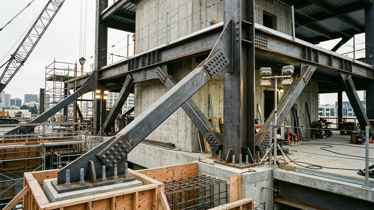
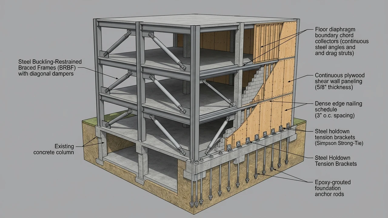
- Buckling-Restrained Braced Frames (BRBF): Highly ductile structural steel diagonal bracing systems consisting of a yielding steel core encased in a concrete-filled steel tube. During earthquake shaking, the steel core yields in both tension and compression without buckling, dissipating tremendous seismic energy and protecting the primary building superstructure from inelastic drift.
- Special Concentric Braced Frames (SCBF) & Moment Frames: Where interior open spans or perimeter window glass must remain unobstructed, structural steel moment-resisting frames (welded wide-flange beams and heavy columns) are installed. Moment frames resist lateral forces through joint flexure rather than diagonal trusses, preserving architectural circulation.
- Reinforced Shotcrete Shear Walls: Pneumatically applied concrete (shotcrete) sprayed against a dense mat of reinforced rebar dowels anchored into existing concrete or masonry walls. Shotcrete shear walls substantially increase lateral shear stiffness, redistributing earthquake loads directly down to the foundation.
- Fluid Viscous Dampers: Hydraulic damping pistons mounted in structural bays that absorb vibrational energy similar to automotive shock absorbers, drastically reducing inter-story drift in multi-story commercial facilities.
Integrating these structural interventions demands surgical pre-construction planning to route steel elements through existing mechanical, electrical, and plumbing risers.
Foundation Tie-Downs, Epoxy Anchor Rods, and Grade Beam Underpinning
A building’s superstructure cannot withstand lateral earthquake loads if it is not securely tied to its subgrade foundation. In older commercial buildings, foundation systems frequently require extensive structural retrofitting:
| Foundation Element | Engineering Specification | Quality Control & Code Testing |
|---|---|---|
| Post-Installed Anchor Rods | ASTM A193 Grade B7 or F1554 Grade 55 threaded rods | High-performance structural epoxy (ICC-ES approved); tension proof testing to 200% design load |
| Grade Beam Additions | Cast-in-place reinforced concrete grade beams (4,000+ PSI) | Continuous #7 and #8 Grade 60 rebar cages tied to existing footings via epoxy dowels |
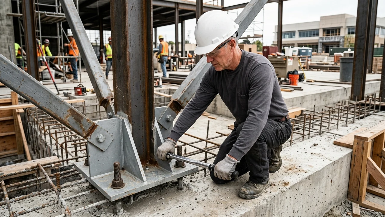
| Structural Holdowns | Simpson Strong-Tie HDU / SDS series heavy steel holdowns | Calibrated click torque wrench verification on all anchor nuts; ICC-ES ESR compliance |
| Diaphragm Chord Anchors | Out-of-plane heavy steel strap ties and thru-bolts | Tying wood or metal roof/floor diaphragms directly to perimeter concrete walls (CBC 1613) |
Specialized hole cleaning protocols – including rotary wire brushing and oil-free compressed air blowing – are rigorously enforced before epoxy injection to guarantee adhesive bond strength.
Diaphragm Nailing Schedules and Drag Strut Collectors
During an earthquake, lateral inertial forces generated by the building’s mass must travel through horizontal floor and roof diaphragms to reach vertical shear walls and braced frames. If horizontal diaphragms fail, the vertical elements cannot function:
- High-Density Plywood Sheathing: Floor and roof diaphragms are reinforced by overlaying 1/2-inch or 5/8-inch structural-rated plywood or oriented strand board (OSB) sheathing with dense edge nailing schedules (spacing 10d common nails at two, three, or four inches on center).
- Steel Drag Strut Collectors: Where open floor layouts create large spans between seismic frames, structural steel angles or continuous steel drag struts must be bolted to floor framing. Drag struts ‘collect’ lateral shear forces from broad diaphragm areas and channel them directly into vertical braced frames.
- Out-of-Plane Wall Anchorage: In tilt-up concrete buildings, the historical failure mode is walls pulling away from roof purlins. Contractors install heavy steel tension ties (such as Simpson Strong-Tie HDU connectors or thru-bolted girder ties) spaced every four to eight feet, anchoring the exterior walls to the interior roof diaphragm.
Field execution must verify nail penetration depths and fastener schedules to ensure calculated diaphragm shear capacities (plf – pounds per linear foot) are achieved.
Role of the Class B Contractor, Special Inspections, and City Signoffs
Under California Building Code Chapter 17, seismic retrofits require mandatory Special Inspection and Testing programs overseen by certified third-party testing agencies and deputy city inspectors:
- Continuous Welding Inspection: Certified Welding Inspectors (CWI) must continuously observe all structural field welds (flux-cored arc welding – FCAW) on moment frames and column splices, conducting ultrasonic testing (UT) and magnetic particle testing (MT) to verify joint penetration without internal slag inclusion.
- Epoxy Anchor Proof Loading: Independent laboratory technicians proof-test a minimum of 25% to 100% of all post-installed epoxy adhesive anchor rods using hydraulic pull-testing rigs to verify that tension pull-out capacities match structural calculations.
- Concrete Rebar and Slump Testing: Slump cone tests and compressive strength cylinder breaks at 7, 14, and 28 days verify that poured grade beams and foundation underpinning meet or exceed specified PSI tolerances.
Upon satisfactory completion of all structural milestones, the general contractor compiles the complete Special Inspection Log, Engineer of Record structural observation letters, and municipal building inspector signoffs, securing final permit closure and documenting the property’s earthquake resilience.